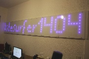
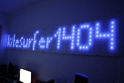
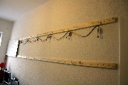
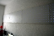
I decided to start a long time planned project in december 2010, which I finished in january 2011. Since then I have a 12ft. long and 20" high LED-matrix with 512 LEDs in my home office.
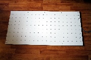
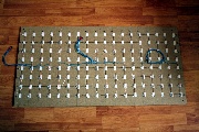
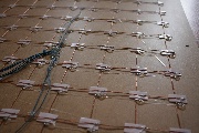
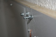
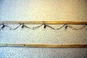
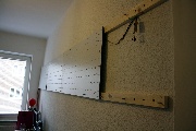
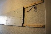
The matrix was built from wooden back boards from shelfs, in which I drilled 64x8 holes for the blue 5mm LEDs. The boards are screwed onto roof laths, which are bolted to the wall. This construction makes it possible to mount the circuit-boards for the columns behind the boards. In front of the boards and the LEDs I mounted frosted acrylic glass (79% light transmittance), to diffuse the light from the LEDs and hide them a little bit.
In the technical point of view it is a quite simple story: The LEDs are switched in rows and columns by using copper wire. There are 8 circuit-boards behind the LED-boards to control the columns. Each of this circuits consists of a 74HC595 shift-register and a ULN 2803A darlington-array. The shift-registers are driven without any magic. Just as you use chained darlington-arrays. The data- and clock-lines are more than 5 meters (16ft) long, but there is no problem driving the shift-registers with higher speed. I added a resistor for each LED to make sure, that the LEDs current is limited. Even if the scanning of the rows stops, the LEDs are under their absolute maximum ratings. It's better for debugging and software development... I put all resistors into sockets. So I can change them to other values, if I have to.
The control of the rows is done by 8 transistors on the main circuit board. They switch +12V to the rows. I chose this, to prevent different brightness on the LEDs because of voltage drop on the 5 meter wires. I had some problems with that using 5V for lots of LEDs connected to long wires. I never saw any brightness problems using 12V for the rows.
The rest of the control-board consists of a ATMEL Mega8 which is running at 14.7456 MHz to keep the UART up at 38400 baud. The controller stores the current frame and keeps the matrix updated by shifting the columns out and switching the right row on. Nothing special here, just matrix-multiplexing.
The controller is connected via a MAX 232 to the serial port of an embedded computer. I used an IGEL Compact 364 LX from ebay for that, running Debian Linux. On the IGEL runns a small server-programm, which forwards UDP-packets received over IPv6 to the serial port and the matrix-controller. There is also an Apache webserver with some php-scripts running. This makes it possible to control the matrix using a normal browser. Because of the IPv6-connectivity the matrix can be controlled directly from the internet. Provided that you have IPv6. I can also control the matrix using the browser of my smartphone. No special apps needed.
Alltogether the matrix is a low-cost project (in relation to the size). All together was around 200€. The most expensive part was the acrylic glass, which costs 100€. The IGEL was 35€ incl. a new 4GB CF-card for the system. I bought the LEDs from China (via ebay) for 20€ (for 1000 pieces). All wood-stuff came from the local hardware store. The most of the electronic-parts lay around or were bought for some cents.
What I have learned:
- Place a multiple of 8 LEDs on a single board. Makes it easier to connect that stuff.
- Keep the roof laths as long as possible. That brings less irregularity to the mounting-screws.
- Buy copper-wire without insulation for the collumns and rows.
Unfortunately there is no documentation at all. I brought the whole hardware directly from my thoughts to life, because it is all very simple designed. If you want to build your own big matrix, you should know enough about electronics and mikrocontrollers. If not: Don't start such a big project! Learn the basics before. It's a good deal of work!
Good news, everyone! There are two videos showing the matrix on youtube:
Update: My matrix at hackaday.com
